Fastest Turnaround Times In The Surveying Industry!


A prefabricated component can match its approved drawing and still encounter fitting problems on site. An opening may narrow through its depth, connection points may sit outside their nominated positions, or the supporting structure may not yet be in its final condition. These differences can create delays and additional work if they are not identified before dimensions are released for manufacture.
For Sydney construction projects, measuring the actual structural interfaces helps the team compare the built geometry with the component's design requirements. MCS Surveyors can assist with obtaining site measurement information, giving engineers and fabricators a clearer understanding of the conditions that need to be considered before fabrication begins. The measurement scope, timing and reporting requirements are vital in making that information useful.
Design drawings describe the intended arrangement of a structure, while site measurements record the geometry that exists at a particular time. Both are necessary, but one should not be substituted for the other when a prefabricated component depends on a close relationship with existing construction.
The purpose of checking these dimensions is not simply to identify construction errors. It is to establish whether the actual interfaces provide the conditions expected by the component's design, allowing the responsible project team to review any differences before they affect fabrication or installation.
An interface is the location where a new component meets, passes through or connects to an existing structure. This might involve an opening, a bearing surface or several connection points. A small difference at one of these locations can matter more than a larger variation elsewhere because it directly affects how the component fits.
For example, a prefabricated frame might need to fit between two structural faces and align with connections above. Each face could be close to its intended position, yet their combined relationship might leave less available space than the fabrication drawing assumes. Measuring only one face would not reveal the full extent of the issue.
Not every departure from a drawing represents a defect. Construction involves specified tolerances, and some connections are designed to accommodate defined variations. Whether a measured difference is acceptable depends on the project's requirements and the assessment of the responsible design professionals, rather than simply on whether the numbers differ.
A drawing may show an opening as a rectangle with a nominated width and height. However, the built opening has depth, corners, surface irregularities and a position relative to the surrounding structure. Its front face may not accurately represent the clearance available further inside.
Imagine a component manufactured to the nominal opening dimensions. Even if its fabrication is correct, it may encounter a projecting edge or a change in alignment through the opening. A width measurement taken at one convenient location would not necessarily identify either problem.
Similar issues can occur when dimensions come from different drawing revisions or use different reference points. A component dimension measured from its centreline cannot be directly compared with a site dimension referenced to an outer face without understanding how the two relate.
Before commissioning measurements, identify which drawing dimensions represent the design intent and which structural features require verification. Include the relevant drawing references in the measurement brief so the surveyor, engineer and fabricator are working from consistent information.
The measurement scope should reflect how the prefabricated component connects to or interacts with the existing structure. Rather than relying on a standard list of dimensions, the fabricator and engineer should identify the features that control fit, support and connection.
A prefabrication survey is most useful when these requirements are established before fieldwork. Requesting measurements of an opening without identifying its critical surfaces or connection relationships can produce accurate information that still leaves important fabrication questions unanswered.
For a structural opening, the required information may include its edges at nominated positions, corner locations and the relationship between opposing faces. The project team may also need levels and positions referenced to an agreed project datum, rather than individual dimensions considered in isolation.
Connection locations require similar attention. A visible plate edge, a connection centre and an adjacent structural face represent different measurement features. The brief should identify exactly which feature needs to be recorded and how it relates to the component's design.
The fabricator can identify the interfaces used to develop the component's fabrication information, while the structural engineer can specify which relationships need assessment. The surveyor can then advise how those features can be measured and reported, including any access or visibility limitations.
For example, an assembly connecting to a structure at several points may require the relative positions of all connection locations. Recording separate distances from unrelated surfaces might not provide enough information to establish whether the connections align as intended. This requirement should be clarified before the survey takes place.
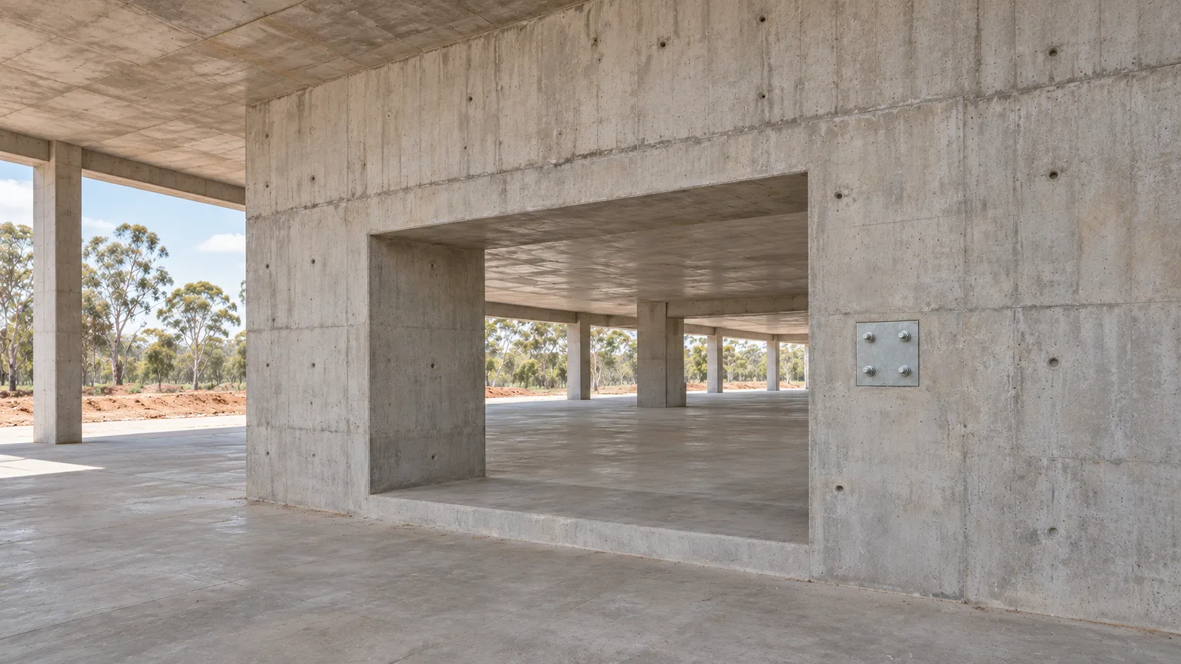
A clear width is only one part of an opening's geometry. Depending on the design, the team may also need to establish if opposing faces are parallel, if the opening changes shape through its depth and if connection points align with the intended component position.
Structural opening measurements should cover the locations and sections that influence the proposed fit. This does not mean every surface needs to be recorded. Instead, the agreed observations should answer the design team's questions without relying on assumptions about unmeasured areas.
Concealed features also need to be identified before fieldwork. A surveyor cannot directly measure a hidden interface simply because it appears on a drawing. The measurement scope should distinguish between accessible features, estimated information and details that remain unverified.
When arranging a survey, pick an approach suited to the information required. Professionals provide further background in their resources on different types of land surveys and when they are needed. For prefabrication work, the survey brief should identify the nominated component interfaces, relevant drawing references and required deliverables.
The required measurement quality depends on the project rather than a generic claim that a survey is highly accurate. Engineers and fabricators need to establish how much variation the design permits and what information is necessary to assess whether the component can fit as intended.
The surveyor can then determine whether the proposed measurement approach, site conditions and reporting format are suitable. This discussion should happen before fieldwork when access is restricted or the available fit allowance is limited.
A fabrication tolerance is an allowable variation defined by the relevant project requirements. Measurement uncertainty refers to the limitations associated with determining and reporting a position or dimension. Although related, these concepts are not interchangeable.
Consider two prefabricated components with different clearance requirements. One might be designed with generous space around its installation position, while another needs to fit between structural faces with very little allowance. The second situation may require more detailed measurement planning because even a small difference could affect the fit assessment.
A fabrication tolerance does not automatically establish the accuracy required for a site survey. The design team must consider how the existing structure's geometry, component manufacture and connection requirements interact. Experts need this information to determine if the requested observations can support the intended decision.
The number of decimal places in a report also does not establish measurement reliability. A dimension displayed to several decimal places may still have limitations arising from visibility, surface condition or the way the measured feature was defined. Understand what the reported information represents, not just how many digits it contains.
There is no universal accuracy figure suitable for every structural interface. The project requirements should establish the appropriate measurement expectations based on the component's design, available clearance and consequences of variation.
A clear measurement brief helps prevent gaps between what the project team needs and what the surveyor is asked to provide. Before arranging the survey, confirm:
The surveyor should also explain any limitations that could affect the results. Where a decision depends on a small dimensional difference, the engineer or fabricator needs enough information to determine whether the survey evidence supports that decision.
When comparing survey proposals, check that each provider is responding to the same requirements. Differences in access assumptions, included features and reporting detail can make similar scopes quite different. Resolving these details avoids additional fieldwork or missing information when fabrication deadlines approach.
Scheduling measurements too early can produce information that does not reflect the structure's final condition. The survey should take place when the relevant interfaces are sufficiently complete and accessible to answer the fabrication questions, while leaving enough time for the professionals to review any differences.
A measurement records the structure as it exists at a specific time. If the surrounding construction or measured surfaces change afterwards, some of that information may no longer describe the interfaces the component will meet. Programme planning should account for measurement readiness and the possibility of targeted rechecks.
Before booking fieldwork, confirm which construction activities need to be finished for the required observations to be meaningful. An opening may already exist, but its final structural edges or connection features might not yet be available. Measuring an approximate outline at this stage should not be treated as verification of the final interface.
Unfinished surfaces require attention. If a later layer, lining or finish will affect the available space, the design team needs to identify how that change will be accounted for. The surveyor should report the surface actually observed rather than treating it as the eventual finished condition.
Temporary works can also influence how measurements should be interpreted. A supported structure may not represent the condition expected at installation. The structural engineer should determine whether the temporary arrangement affects the fit assessment and if measurements are needed at a different construction stage.
Access is another part of survey readiness. Stored materials, temporary barriers and incomplete access arrangements may prevent the observation of critical features. Confirming these constraints allows the team to decide whether to reschedule, revise the scope or accept clearly documented omissions.
Later alterations to an opening, connection position or supporting surface can make an earlier measurement unsuitable for fabrication decisions. Even a local change may affect a critical fit location. Its significance depends on how it relates to the component rather than simply how large the alteration appears.
Keep the measurement date and observed site condition attached to the results. If construction continues around the interfaces, the person coordinating fabrication should have a process for identifying changes and referring them to the relevant reviewers before relying on earlier information.
This does not necessarily mean repeating the entire survey. The surveyor and design team may identify selected features that need remeasurement, provided the remaining information is still suitable for use. The extent of any recheck should reflect the changes and their potential consequences.
Where the construction programme requires early information, distinguish preliminary measurements from those intended to support fabrication release. Record unresolved interfaces and specify which construction milestone or event will trigger their verification. This prevents preliminary information from being mistaken for a final dimensional record.
A discrepancy between site measurements and design drawings is a reason to investigate, not an automatic instruction to alter the structure or component. The first step is to establish that the measured and design information are being compared on the same basis. The difference should then be referred to the people authorised to assess its implications.
Clear measurement records make this process easier by showing where the variation occurs, which component interface it affects and how it relates to the approved design. A general statement that an opening is out of position provides less useful information than a defined comparison between nominated features.
Start by checking the drawing revision, reference points and definition of each measured feature. Confirm that a structural face has not been compared with a finished face, or that dimensions taken at different locations have not been treated as equivalent.
The comparison should also account for measurement limitations. A small apparent difference may require further clarification before it can support a firm decision. If the available information does not resolve the issue, ask the experts if additional measurements or observations are necessary.
The responsible engineer and fabricator should compare the verified geometry with the applicable project tolerances and connection requirements. A difference may fall within the intended allowance, or it may require a design review. The survey result alone does not establish either outcome.
If clarification is needed when interpreting annotations, levels or reference points, professionals also provide an explanation of how to read a surveyor's report. Project-specific questions should still be directed to the surveyor who prepared the information.
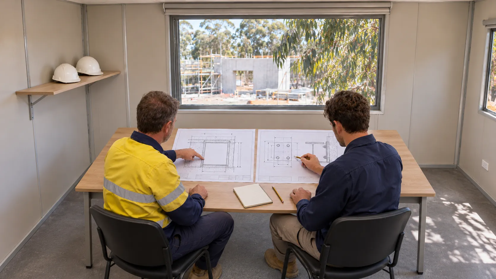
Send the relevant measurement information, drawing references and discrepancy details through the project's agreed review process. Identify the affected component or interface and whether fabrication is waiting on a decision. This gives reviewers the context they need without requiring them to reconstruct the issue.
Any proposed response involving structural components or connections must be reviewed by a structural engineer. A dimensional mismatch should not be treated as permission for site cutting, drilling, welding or connection adjustments. The acceptable response depends on more than physical clearance. SafeWork NSW’s guidance on structural design responsibilities also highlights the importance of communicating safety concerns to the designer and resolving them before proceeding.
The fabricator also needs the reviewed outcome in a form that can be incorporated into controlled fabrication information. Verbal acceptance of a site dimension is not a substitute for an agreed record identifying what has changed and which information now applies.
If revised work changes an interface, confirm whether follow-up measurements are required before fabrication is released. Keep the original observations, reviewed decision and replacement information distinguishable so superseded dimensions do not continue circulating alongside the current issue.
Reliable coordination depends on separating two questions: what geometry exists on site and whether that geometry is acceptable for the proposed component. The surveyor provides evidence for the first question, while the responsible project team uses that information alongside the design requirements to answer the second.
On construction projects, several parties may handle the same dimensions before fabrication begins. Clear responsibilities help prevent a measured position from being mistaken for engineering approval or a reviewed design change from being mistaken for confirmation that the site has already changed.
The surveyor's agreed scope should define the features observed, references used and information supplied. As-built interface measurements should be traceable to the relevant locations and measurement date, with limitations identified wherever access, visibility or incomplete construction affects the results.
The report describes the physical evidence within its agreed scope. It does not automatically establish structural adequacy, approve a revised connection or guarantee that a component will fit. Those conclusions involve design and fabrication considerations beyond recording site geometry.
This distinction also matters when a report includes comparisons with nominated design positions. Showing a difference helps the project team locate and understand an issue, but a comparison is not necessarily an acceptance decision. Any annotations or status descriptions should be interpreted according to their intended meaning and the agreed reporting scope.
When looking for surveyors in Sydney, provide shortlisted providers with the component details and specific interface requirements rather than requesting a site check. Confirm the proposed measurement scope, including access, timing, reference information and the intended use of the deliverables.
The structural engineer assesses the relevant design implications, while the fabricator considers how the reviewed geometry affects its fabrication information. The contractor coordinates site readiness, current documentation and the agreed release process. Exact responsibilities should be confirmed for each project rather than assumed from job titles alone.
Before manufacture proceeds, identify who is authorised to accept the measured interfaces and who releases the component for fabrication. Surveyors should not have to infer acceptance criteria that the design team has not supplied, and the fabricator should not have to guess whether an unresolved discrepancy has been approved. For work covered by the Design and Building Practitioners scheme, the project team should also check the NSW requirements for regulated designs and variations before proceeding with changes.
The final handover should clearly separate measured results, approved design decisions and unresolved issues. Include the applicable survey issue, reviewed drawing revision and any qualifications that remain relevant to the component's fit. Where acceptance depends on later construction work or another measurement, state that requirement explicitly in the release process.
Keep these records available to the people coordinating installation. If the structure changes after fabrication release, the project team needs to know which measurements informed the component's dimensions and who is responsible for reviewing the effect of that change.
Accurate structural interface measurements identify potential fitting problems before prefabricated components reach the construction site. However, useful results depend on more than measuring a few opening dimensions. The survey scope must reflect the component's actual connection requirements, account for site conditions and provide information that engineers and fabricators can assess against the approved design.
Involving the surveyor early gives the project team an opportunity to agree on measurement requirements, identify access limitations and schedule fieldwork around the structure's construction progress. Any differences can then be reviewed by professionals before they affect fabrication or installation.
MCS Surveyors assists with site measurement requirements and provides survey information to support construction coordination. Discussing the required interfaces, drawing references and reporting expectations before fieldwork ensures the measurements address the project's needs and gives a clearer basis for making decisions.